No Power In Satellite Receiver Repaired- Model: Top field TF3000FI
An old man who lives nearby my shop brought this satellite receiver for repair. Topfield is a good satellite receivers and usually the main cause of them going bad usually capacitors.
The main problem would be, are they bulged and very easy to see find or we have to check them one by one? Let us find out.
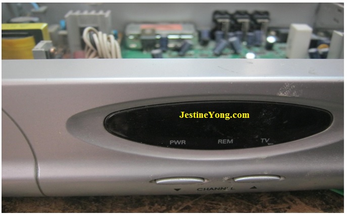
The first thing I noticed after I powered up the device is the ticking noise that was coming out of it which confirmed my experienced guess.
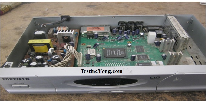
As I took the top off and exposed what inside, I headed directly to the power supply and started doing measurements.
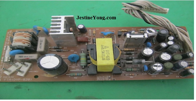
It was very clear to me that it will take longer than expected to repair this device since I do not see any bulged capacitors. Let the fun begin.
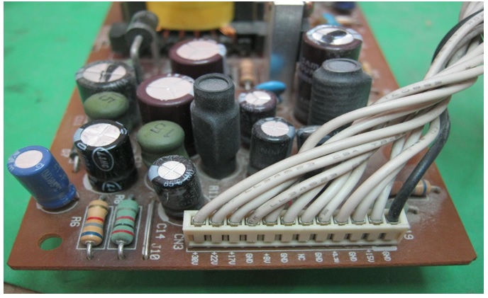
There is a way to check the capacitors other than using the ESR meter and that to follow the bad line. For example, you can see measurement printed on board.
That is my clue to bad capacitors. The first reading was 38 volts. When measuring that with my multimeter, I got 45 volts which is way too high for that line. I traced all the capacitors in there and replaced them. I powered the device and guess what? The device came on for about two minutes then it started shutting on and off. I was getting close. So I tested the next line which was 22 volts and the reading there was 35. Again, that was too high so I traced that line and replaced all the capacitors there.
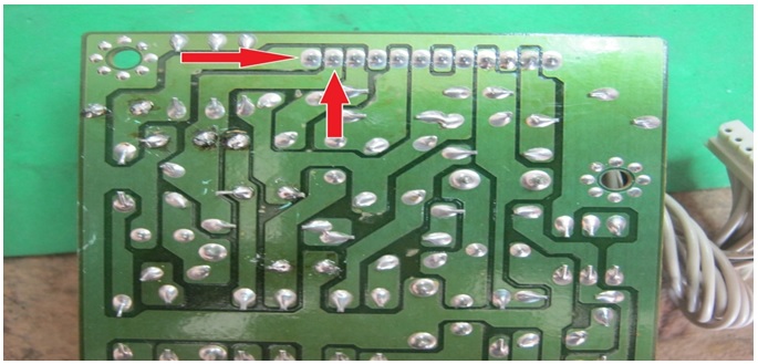
This view is from the other side of the board and you can see the traced that I followed in this repair.
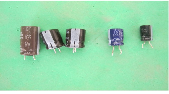
Here are the bad capacitors that I found in the device.
1000uf/16 volts
220uf/35 volts x 2
47uf/50 volts
100uf/35
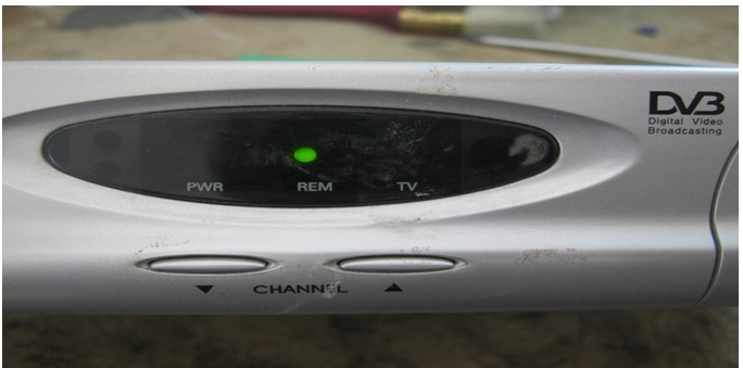
As you can see, this method worked out fine. This is the first time that I used this method of repair. It really worked. In other words, fix the line that need fixing and do not mess with the things that are ok. A repair technician and my friend suggested this method of repair. You as technician might not follow this way of repair, that is understandable but you can use any way that fits the need.
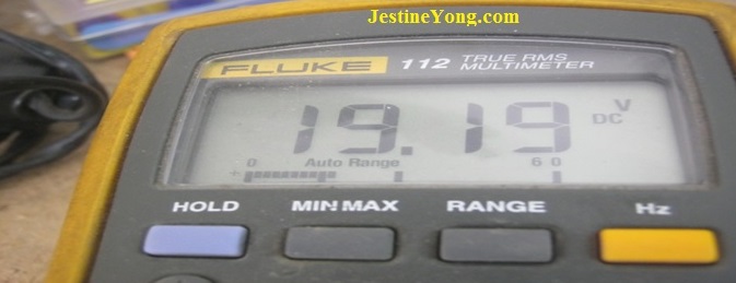
This was the final reading on the output of the LNB connection.
Mission accomplished.

This article was prepared for you by Waleed Rishmawi, one of our ‘Master Authors’ and currently working in the Bethlehem area of Palestine repairing electrical and electronic equipment.
P.S- Do you know of any your friends who would benefit from this content that you are reading now? If so, forward this website to your friends or you can invite your friends to subscribe to my newsletter for free in this Link.
Note: You can check his previous repair articles in the link below:
https://www.electronicsrepairfaq.com/dynamic-stereo-headphone-repaired-sony-mdr-7506


Another way can always be to use an oscilloscope and look for a big ripple on top of the DC voltage. Measuring a power supply’s ripple with my Tektronik oscilloscope also gives me at the same time the voltage level and or frequency. Information which my digital meter isn’t capable in showing.
True but if you do not have a oscilloscope there is another way of doing it. Thanks for sharing
what is the voltage on that line after replaced capacitor .
Both were back to normal
Hi Mr waleed very nice explanation thanks for sharing.
THANKS VERY NICELY EXPLAINED AND VERY INFORMATIVE FOR TECHNITIONS.
Thanks its my first time to hear of this method I will try it on my repairs thank you Jestine for bringing a recap of previous repairs I almost missed this one.
Good job Waleed
Thanks a lot.
Thanks Mr. Waleed.I have a strong receiver srt 4922 that if i power it, what it shows is Lnbf how can i solve this problem please help!
good sharing
Thanks I will try this method on my stg 4922