Day/Night Switch Sensor Light Repair (With Hand Drawn Schematic Diagram)

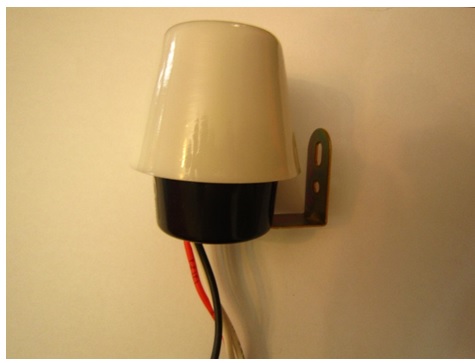
Recently I received this photocell switch that was not working. I opened the machine and start to study to see why is not working. And the result is this article:
Automatic photo cell jobs
-Automatically on/ off the lights in the entrance of buildings / parking /gardens / yards and or billboards…..
-Automatically on / off the lights inside the stores and shopping stores.
-To save money in consumption of electricity and keeping life span of lights.
– Automatically switch the light of streets and .public passages.. so and so.. the power supply of this machine:
Is a very good example of transformer and mosfet less power supply. is very cheap and light weight the architecture is based on just using the resistors diodes and caps with very precise calculation of values of components
LDR: Light dependent resistor:
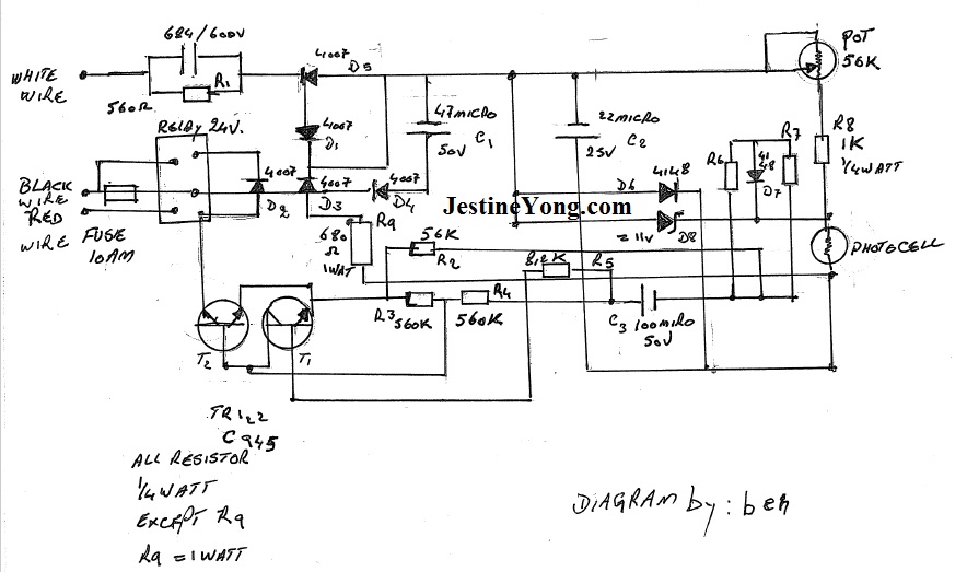
The principal of photocells are based on a chemical compound (selenium sulfide: SeS2 ) that shows different resistance value in front of flow of photons .in another word in day time and enough light this compound shows resistance and cut the circuit and in night time during the darkness lets the electron flow in the circuit and act as a switch and trigger the relay and relay make contact inside and let the live line of electricity reach to the lamps. In the circuit two C945 series NPN transistors are installed and their emitters joined together to amplify the difference s of voltages of photo cell and deliver and translate these for relay to let the lights on or off

Diagram of circuit of photocell switch
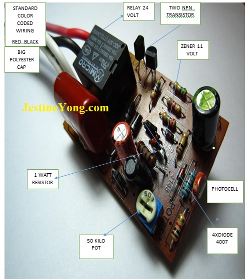
The relay of machine is: JQC3FF this is a subminiature power relays single – pole 10 Amp 24 Volts that I found it defected

Four diodes 1N4007 acts as part of DC power supply and rectify the AC entrance voltages .one pot.56k is present in this machine by changing the value of the resistance of pot the sensitivity of photocell against light can be change and desire on/off mod of lights can be achieved.

R9 biggest resistor 1 watt in the circuit act as decreasing entrance AC voltages since this resistor has a full tension job seems get very hot and PCB color around the resistor was turned to dark brown and even black color but the value of resistor was good.
The machine has two incoming wire and one out going:
Incoming wires:
One is white color wire that is neutral line of electricity
That goes directly to polyester cap 684/600 volt
That cap is installed parallel with R1 resistor 560 ohm ¼ watt that act as a filter for entrance AC and act to prevent unwanted harmonies of AC
I have to mention: that this white wire is a sub extension of neutral wire that goes directly to the lamps. Another entering wire to machine is black wire.
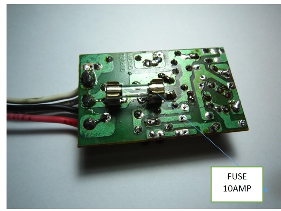
Black wire: that is live line and directly goes to one pole of relay here also 10 AMP fuse is present to protect the machine against unwanted spikes.
Outgoing wire is red:
Red wire is live line that is coming out of the machine and directly coming from another pole of the relay and by commend of relay this wire will contact with black wire and will light up the lights. Zener diode 11 volt also act as a voltage regulator and supplying voltages for photocell. On the PCB there are 3 electrolytes caps that their job is purifying the DC voltages.
By replacing the relay the machine returned to life all other component were good to know how to test the relay I refer you to page 163 of Jestine Yong’s Ebook here.
Note: I repaired this machine with ohm check method only and with no power on it.

This article was prepared for you by Mr Beh from Iran
Please give a support by clicking on the social buttons below. Your feedback on the post is welcome. Please leave it in the comments.
P.S- If you enjoyed reading this, click here to subscribe to my blog (free subscription). That way, you’ll never miss a post. You can also forward this website link to your friends and colleagues-thanks!
Note: You may check out his previous repair articles in the below link:
http://jestineyong.com/led-lamp-repaired/


Very detailed and informative article. Professional service too! Thanks for sharing.
Hi Parasuraman
Thanks for your supports.
beh
Nice repair and interesting schematic you have drawn Mr.Beh. I will have to examine the circuit more closely before I completely understand it. The top diode looks like a thyristor but is also a 1N4007 diode, so the top 2 1N4007 diodes are connected anti-parallel?
Hi Albert
As you told this circuit needs enough time to explore inside. seems very simple but is complicated it is a mixture of AC/ DC circuits. thanks for supports
beh
I think this article needs second part and i will .
Great job Beh. Congrats.
Thanks Dear HUMBERTO.
Good job, Beh. It’s been a long time since I heard anything from you! I thought about asking Mr. Yong if you were still kicking.
I have a Night Light on my large breadboard where the LED’s are controlled with an LDR through the #4 reset pin of a 555 IC.
I’m glad to see that you are still with us.
Hi Robert
Yes i know . i am coming back from a long absence due to travel since MAY 2016.
but i return back with my articles. yes you have the right ,also this machine is available in the market that works with the help of ic s . but it has another story .
I am always thankful of your supports like this time .i never left this group.
cheers
beh
Good job thanks.
Hey Danlami
thanks
and
cheers
beh
Nice hearing from you beh welcome back
TABREZ KHAN
Yes i am happy too . but this is your first comment during last 10years that i am receiving from you!.
beh
Hi Beh
I am Iranian too and wanna know how can I join this group cuz I wanna put my case studies for peoples like you but I don’t know how to do it. Can you help me and describing that how can I join this little group for sending my experiences to it?
with best regards
Mehdi
from Dehloran-Ilam-Iran
ok MR MEHDI just make your articles send it to manger of web log MR JESTINE YONG he will evaluate your article and will tell you is it publishable or not?
You can go to contact us in this blog to email him
thanks
happy you are joining us.
beh
May be you can tell me what fault on my day/night switch
When it night time it active the light on
When power failure,after power is restored,the light not comming on again., But if I bang it slightly it came on
The switch did see a moons already
It is old
A
Dear Beh fromIran-The Value of R1 parallel with C1 is not 560 but that is value 560 Kohm.Its duty is re-empty C1 when it out main voltage
relay positive conection not conected,you drive negative through transistor
please send the clear relay connection
Hi
I have the same problem with this light sensor and The problem was the potentiometer that was open circuit